Site Summary - New UI
SECURITY Refer to SITES > Sites in Security Level Details - Permissions
NAVIGATION New UI > Sites > View all
NAVIGATION New UI > Sites > click the name of a site
About
A site lets you group devices together. You can define sites in the way that suits you best. If you are a Managed Service Provider, a site might mean a customer. If you are supporting one large IT organization and your devices are spread out over a number of locations, a site may be an office department or a location. Whatever your situation, you can set up your sites as per your preference.
NOTE Note that a device can only belong to one site, but it can be moved between sites as required.
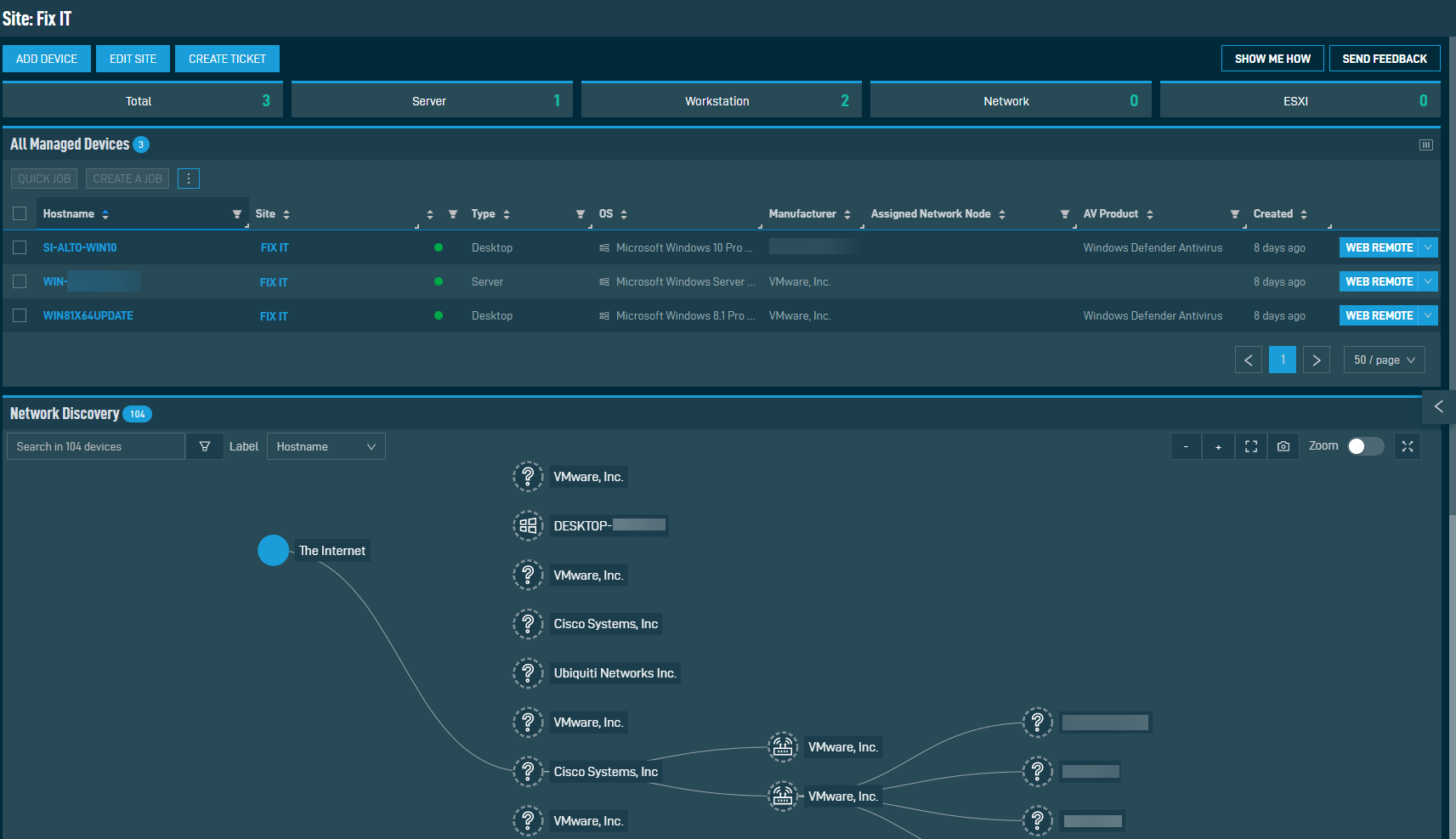
Click the Add Device action button at the top of the page. For more information, refer to Adding a device - New UI.
Click the Edit Site action button at the top of the page. For more information, refer to Editing a site.
Click the Create Ticket action button at the top of the page. For more information, refer to Creating a ticket - New UI.
Refer to List of devices.
Refer to Action buttons.
Refer to Remote support actions.
In order for devices to be discovered on your network, an online device within your site must be nominated as a Network Node with scanning enabled. This device can be a Windows, macOS, or Linux device. For information about how to add a device, refer to Adding a device - New UI. For information about how to nominate a device as a Network Node, refer to Network Node.
NOTE For information about how to nominate a device as a Network Node in the current UI, refer to Edit device details. Note that in the current UI, Linux Network Nodes are not able to perform network scans. Refer to Requirements to nominate a device as a Network Node.
Once this is completed, scanning will begin. It may take some time for the scan to complete depending on how large your network is. The network topology map will appear when scanning has completed. You will need to refresh the page to view the results.
IMPORTANT For best results, SNMP credentials should be configured. Refer to SNMP Credentials in the current UI and SNMP credentials in the New UI.
IMPORTANT It is strongly recommended that a device acting as a DHCP server NOT be nominated as Network Node with scanning, as network topology mapping requires UDP port 67 to be free for the identification of network devices using DHCP fingerprinting.
NOTE Devices must support the industry-standards RFC 1493 and RFC 4363 in order for the network topology map to be created.
NOTE If scanning is turned off on the designated Network Node, the network topology map and devices will disappear after one week.
Select the map icon at the top of the Network Discovery card.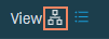
There are various actions you can perform:
| Field/Icon | Description |
|---|---|
Search |
Enter a hostname, IP address, MAC address, manufacturer, or NIC vendor to search for a device. The search results will be narrowed as you type and non-matching devices will appear dim within the map. |
Filter |
Click the filter icon to view the filtering options. Select to filter on device type, online/offline status, Managed/Unmanaged status, and whether or not devices have open alerts. |
Label |
Select how to label devices in the map. |
Zoom out/zoom in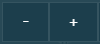 |
Zoom out or in on the map. |
Fit to screen |
Click to show the entire map within the card. |
Save topology as image |
Click to save a screenshot of the map as currently displayed within the card. |
Zoom toggle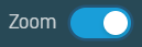 |
Toggle to enable zooming in or out of the map using the mouse wheel instead of the zoom in/out buttons. |
Full screen/exit full screen |
Click to enter full screen mode. Click the X to return the screen to normal. |
Within the map, various icons represent different types of devices. 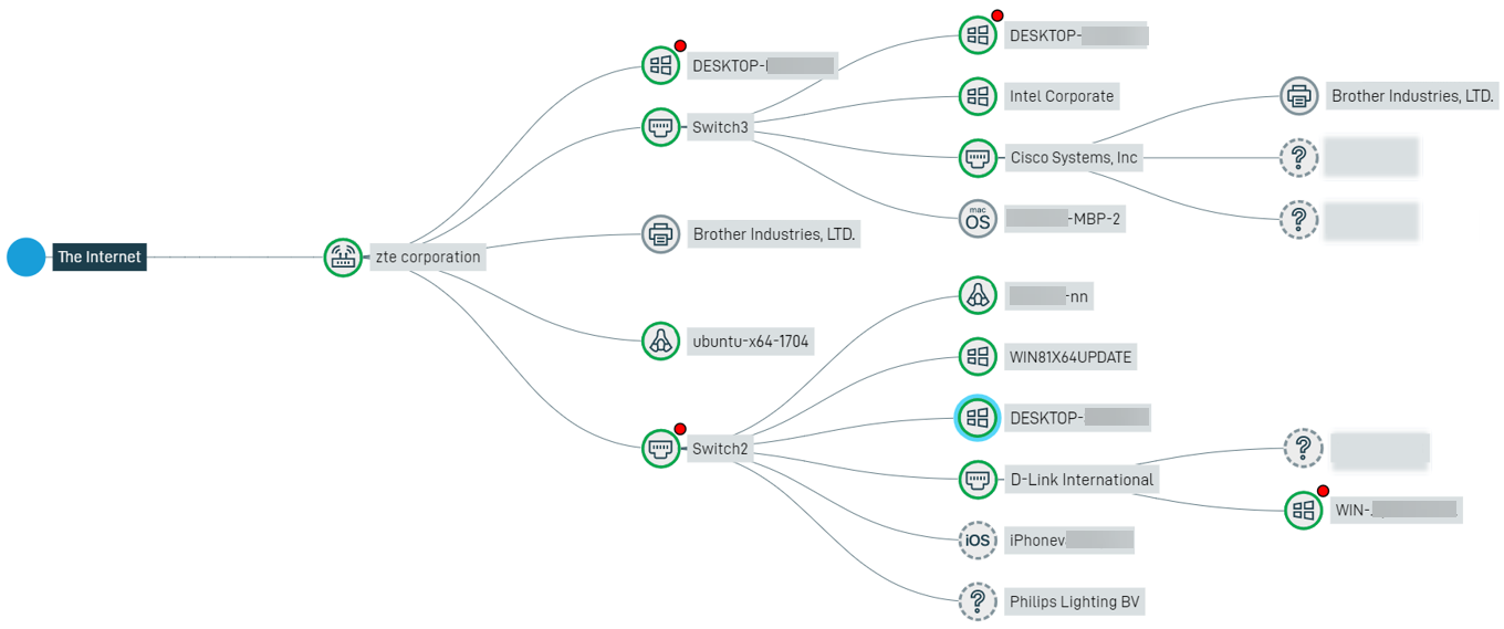
Visual indicators for devices are as follows:
| Indicator | Description |
|---|---|
| Solid line | Indicates the route from one device to another. |
| Blue circle | Indicates the currently selected device. |
| Green circle | Indicates the device is currently online. |
| Dashed circle | Indicates an Unmanaged device. |
| Solid circle | Indicates a Managed device. |
| Red dot | Indicates the device has one or more open alerts. |
Hovering over a device in the map will display additional details about the device.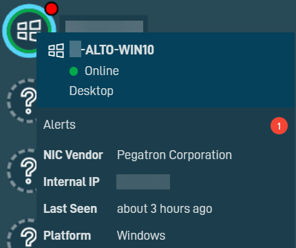
Clicking on a device in the map will open the Device pane. 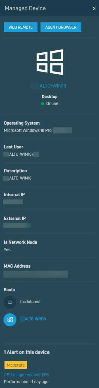
The details displayed within the pane depend on the type of device. If the device is online, you can access it remotely via a Web Remote or Agent Browser session by clicking the respective action buttons at the top of the pane. Refer to Action buttons for more information. In addition, clicking a hyperlinked device name opens the Device Summary page for that device. Refer to Device Summary - New UI. If the device has open alerts, clicking a hyperlinked alert name opens the Single Alert View page for that alert. Refer to Single Alert View - New UI.
Select the detailed view icon at the top of the Network Discovery card.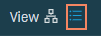
Refer to Column Chooser field definitions for descriptions of the available fields in the device list.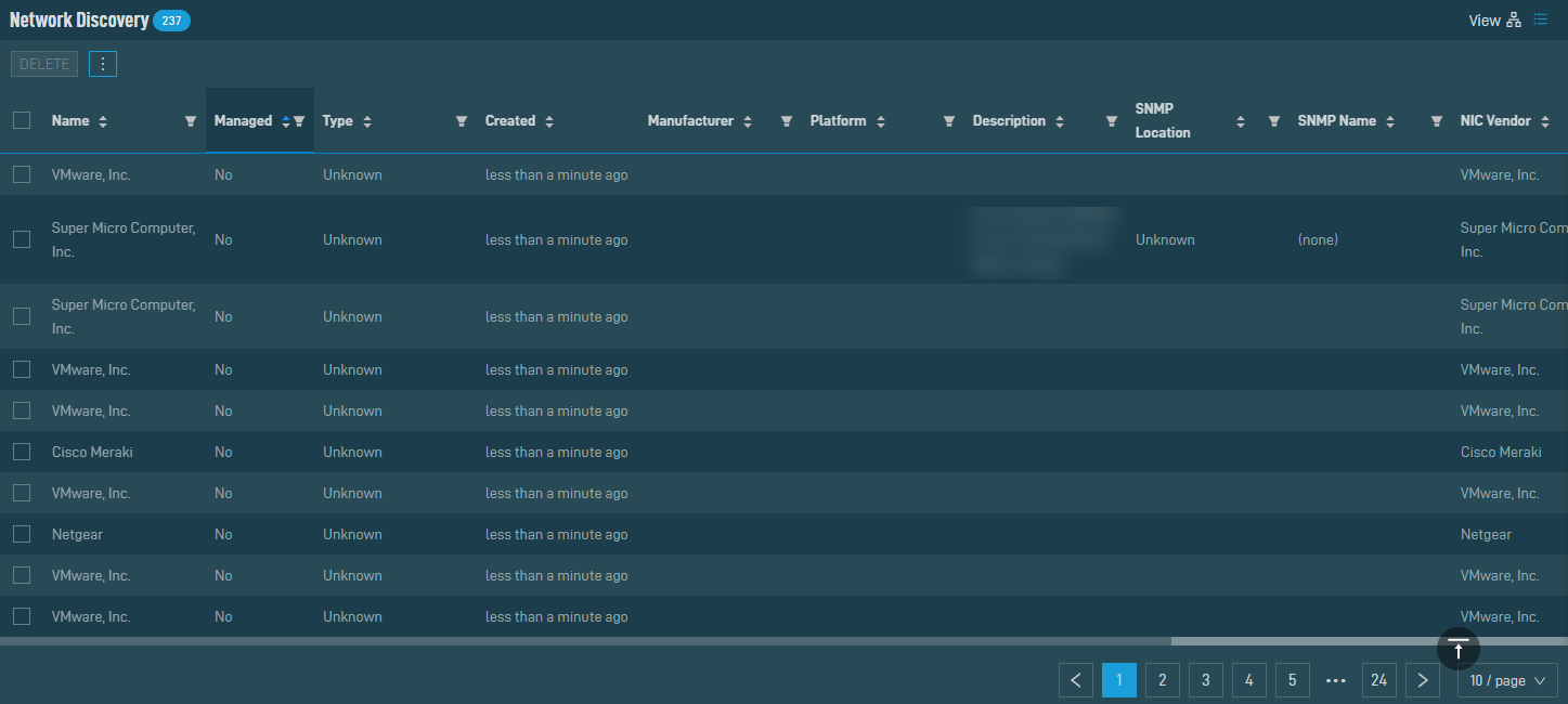
There are various actions you can perform:
| Action Button | Description |
|---|---|
|
Delete |
Refer to Action buttons. |
| Export Selected Rows to CSV | In the confirmation dialog box, select whether to show table headers in the file by toggling the Show table headers in the exported CSV button. Select OK to download the file. Any column selections or filters that have been applied to the table will also be applied in the CSV file. A maximum number of 500 rows can be exported to a single CSV file. The Export All (Max. 500) Rows to CSV action is available without selecting any row in the table.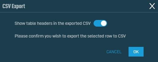 |
| Export All (Max. 500) Rows to CSV | |
| Uncheck All | Deselects all selected rows. The number of selected rows is indicated in parentheses and next to the Row Actions icon. |
The number of results displayed can be specified by selecting the desired number from the drop-down menu at the bottom of the table. This selection will persist the next time the page is accessed.


